Inductive conductivity measurement in industrial metrology
- contact: Marco Völker, Olaf Dössel
- project group: Messtechnik/Signalverarbeitung
Inductive conductivity measurement in industrial metrology
Inductive conductivity sensors generate a current in the medium using a coil, and measure the current with a secondary coil (see picture).
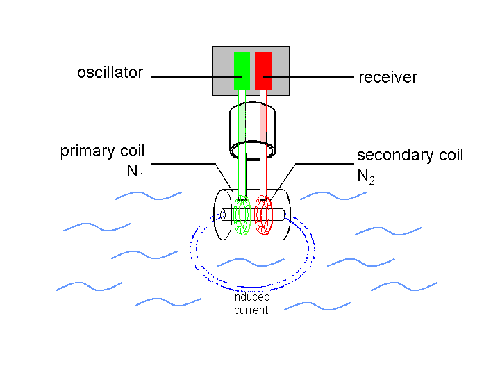
The aim of this project is the modelling, simulation, optimisation and evaluation of inductive conductivity sensors for industrial metrology. This project is handled in cooperation with an industrial partner.
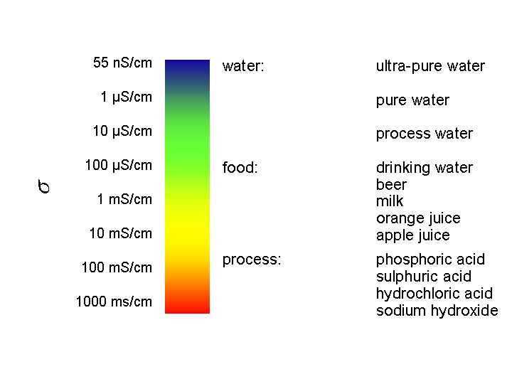
The parameter „conductivity“ is an important parameter for controlling of industrial processes. The conductivity in process technology ranges from 55 nS/cm at ultra-pure water applications (eg. for pharmaceutical products) to more than 1000 mS/cm when using hot acids and leaches (see picture). For comparison: The drinking water in the city of Karlsruhe has a conductivity from approx. 640 µS/cm to 680 µS/cm.
The parameter „conductivity“ is an important parameter for controlling of industrial processes. The conductivity in process technology ranges from 55 nS/cm at ultra-pure water applications (eg. for pharmaceutical products) to more than 1000 mS/cm when using hot acids and leaches (see picture). For comparison: The drinking water in the city of Karlsruhe has a conductivity from approx. 640 µS/cm to 680 µS/cm.


Due to the non-contact measurement principle, inductive conductivity sensors lack the problems connected with electrode sensors, like uncontrollable contamination and polarisation effects. A disadvantage of today’s inductive conductivity sensors is the reduced sensitivity and the relatively high lower measurement limit (approx. 100 µS/cm). This prevents inductive conductivity sensors being used in pure water applications.
The aim of this project is reducing the lower measurement limit by systematic model- ling, simulation and optimisation.
Basically, the project can be divided into 3 main areas:
The aim of this project is reducing the lower measurement limit by systematic model- ling, simulation and optimisation.
Basically, the project can be divided into 3 main areas:
- Modelling and simulation
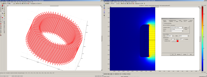
Using the programme „Comsol Multiphysics“, an FEM (finite element method) model of a toroidal coil is generated. This will allow the simulation and judgement of the coil’s parasitic effects by numerical field calculation (left picture). Also, axial symmetric models of a conductivity sensor are investigated (right picture).

- Measurements and electrical replacement circuit
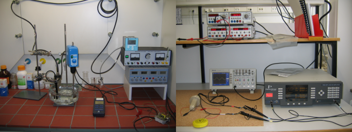
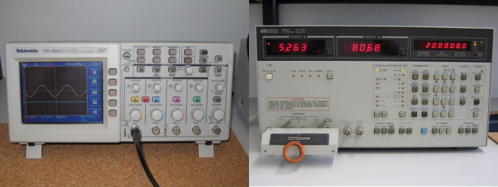
Another aim is to build up an electrical replacement circuit of the Sensor using PSpice. The replacement circuit shall include all effects important for the measurement result. For doing this, it is necessary to perform measurements with existing sensors. These measurements are done either in the hardware laboratory or in a chemical laboratory. For performing the measurements, a number of measurement equipment is supplied, amongst others a high frequency Lock-In amplifier (PerkinElmer 7280, see figure below right), a 500MHz four channel digital oscilloscope (Tektronix TDS2024, figure far below left) and a low frequency impedance analyser (HP4192A, figure far below right).


- Hardware set-up
For the examination of different new sensor principles, sample sensors and circuits using the new principle are set up. The new measurement principles are judged by different criteria (eg. sensitivity, usability in practice and costs). For the design of printed circuit boards, complete exposure and etching equipment is supplied.
In all areas of the project, student research and final year projects (diploma thesis) can be assigned. A listing of currently available student research and final year projects can be found following the topic “Diploma thesis” on the main website. Students interested in working on the projects can contact me at any time.

